Reading Thermal Images of Bearings: Genuine Supplier for Bulk MRO Orders
A hot spot on a thermal image rarely means the bearing itself is failed.
Accurately reading thermal images of bearings requires correlating temperature distribution with operating parameters and vibration data to identify external friction sources, rather than assuming internal raceway damage necessitates immediate replacement.
The glare of infrared cameras can be deceiving. In the harsh environment of a cement plant in the Middle East, I once watched a maintenance manager point at a bright red patch on a kiln support roller bearing and demand an emergency air shipment of replacements. The thermal signature was undeniable, showing a significant temperature differential. However, replacing the unit without further investigation would have been a costly mistake. By combining the thermal data with a quick vibration spectrum check and a physical inspection of the seal assembly, we discovered the heat was generated by excessive friction from an overly tight seal, not by internal bearing fatigue. This experience underscores why learning how to read thermal images of bearings is critical for avoiding unnecessary downtime and parts waste. [NEED_CITE: common misdiagnosis rates in industrial thermography]
Understanding these nuances transforms maintenance from a reactive cost center into a strategic reliability function. For operators managing heavy machinery in mining, steel, or power generation, the ability to interpret these images correctly prevents blind replacements and ensures that genuine components are installed only when truly necessary.
Why Do Bearings Overheat?
Internal damage is often the last suspect, not the first.
When a bearing runs hot, the instinctive conclusion is that the rolling elements or raceways are failing. While this is possible, external factors are frequently the true culprits. Distinguishing between internal friction and external assembly issues is the first step in effective diagnosis. [NEED_CITE: ISO 15243 failure mode classification]
Common external causes include:
- Seal Friction: As seen in the kiln case, improper seal clearance or aggressive lip seals can generate substantial heat at the outer ring interface.
- Misalignment: Angular or parallel misalignment forces the bearing to operate under uneven load distributions, creating localized hot spots.
- Over-lubrication: Excessive grease churning within the housing creates viscous drag, raising temperatures uniformly across the assembly.
- External Heat Sources: Proximity to furnaces, steam lines, or process heat can radiate onto the housing, mimicking internal failure.
Internal causes, such as spalling or cage damage, typically present with different thermal patterns and are almost always accompanied by specific vibration signatures. Relying solely on temperature readings without context leads to false positives. A comprehensive approach to reading thermal images of bearings involves ruling out these external variables first.
How to Capture Accurate Thermal Images?
Emissivity settings determine whether you see reality or reflection.
Capturing a usable thermal image requires more than pointing a camera at a machine. Environmental factors and surface properties significantly affect accuracy. Without proper setup, the data collected may be misleading, leading to incorrect maintenance decisions. [NEED_CITE: ASNT guidelines for industrial thermography]
Key steps for accurate capture include:
- Set Correct Emissivity: Metallic surfaces, especially polished bearing housings, have low emissivity and high reflectivity. Applying matte black tape or paint to the measurement area ensures consistent readings.
- Account for Ambient Conditions: Record ambient temperature and airflow. Drafts or direct sunlight can skew surface temperature readings.
- Maintain Proper Distance and Angle: Stand perpendicular to the target surface to minimize reflected energy from other heat sources.
- Allow Stabilization Time: Ensure the machine has run long enough to reach thermal equilibrium before capturing images.
Ignoring these factors can result in temperature errors of several degrees, which might be the difference between a normal operating range and a critical alarm. When training teams on how to read thermal images of bearings, emphasizing these procedural controls is essential for data integrity.
How to Interpret Thermal Patterns?
The location of the hot spot tells the story.
Once a valid image is captured, the pattern of heat distribution provides clues about the root cause. Different failure modes produce distinct thermal signatures on the outer ring, inner ring, and housing. [NEED_CITE: Vibration Institute thermography interpretation standards]
- Uniform Housing Heat: Often indicates over-lubrication or general overload. If the entire housing is warm but not excessively hot, check grease volume and type.
- Localized Outer Ring Hot Spot: Suggests seal friction, external rubbing, or static misalignment. The heat is concentrated where the component interacts with the housing or seal.
- Inner Ring Dominant Heat: May point to slippage on the shaft or internal rolling element damage. This is harder to detect directly due to the rotating nature of the inner ring, but heat conducts through the rolling elements to the outer ring.
- Asymmetric Heating: One side of the bearing is significantly hotter than the other, indicating angular misalignment or uneven loading.
Interpreting these patterns requires familiarity with the specific machine configuration. A hot spot on a conveyor pulley bearing might mean misalignment, while the same pattern on a pump could indicate coupling issues. Mastering how to read thermal images of bearings involves recognizing these spatial relationships.
What Other Data Should You Cross-Check?
Thermography alone is insufficient for definitive diagnosis.
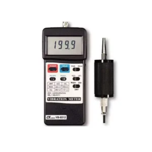
Temperature is a lagging indicator. By the time a bearing shows significant heat, damage may already be advanced. To confirm root causes and avoid false positives, thermal data must be cross-referenced with vibration analysis and operational parameters. [NEED_CITE: ISO 13379-1 condition monitoring guidelines]
| Data Source | What It Reveals | Correlation with Thermal Data |
|---|---|---|
| Vibration Spectrum | Identifies specific fault frequencies (ball pass, cage, etc.) | Confirms if heat is from internal damage or external issues |
| Load Parameters | Shows actual operating load vs. design capacity | Explains uniform heating due to overload |
| Lubrication History | Tracks grease type and replenishment intervals | Links uniform heat to over-lubrication or wrong grease |
| Ambient Temperature | Provides baseline for differential calculation | Adjusts threshold alarms for seasonal variations |
For example, a steel mill roll neck bearing showing a gradual temperature rise might correlate with increased production loads. If vibration data remains clean, the heat is likely due to operational stress rather than impending failure. Conversely, if vibration spikes accompany the temperature rise, internal damage is probable. Integrating these datasets ensures that when replacements are ordered, they are justified. This holistic approach is central to effectively reading thermal images of bearings.
In complex industrial environments, identifying the true root cause—whether it is a seal issue, misalignment, or genuine bearing fatigue—determines the correct corrective action. Once the diagnosis is confirmed, sourcing the right replacement becomes critical. Ensuring traceability and authenticity of components like SKF, FAG, or NSK bearings guarantees that the new installation performs as expected. Technical teams often provide on-site failure analysis to support this process, helping operators distinguish between assembly errors and component defects. This level of support ensures that maintenance efforts lead to long-term reliability rather than repeated failures.
Conclusion
Diagnosis precedes replacement.
Reading thermal images of bearings is not just about spotting hot spots; it is about understanding the mechanical context behind the heat. By combining thermal data with vibration analysis and operational insights, maintenance teams can avoid unnecessary replacements and address root causes effectively. This disciplined approach minimizes downtime and optimizes maintenance budgets.
Have a shutdown list?
Send the whole list in one message. Spare Parts Company quotes each SKF bearing and its accessories line by line, with availability and estimated lead time.